
Abstract In the last decade, micro aerial vehicles (MAV) have shown significant potential as miniature unmanned aircraft for dual use- surveillance and reconnaissance purposes. The selection of correct combination of propulsion system, vehicle aerodynamics and its payloads for different missions is a very important step in the design of this class of vehicles. 1. Introduction. The main objective is to find a very low price alternative propulsion system for a 200-300 grams MAV which is able to assure a vertical take off and obtain good performance maps. The hybrid propulsion system consists of a micro rocket for vertical take off and short time accelerations combined with an electric engine could be an interesting solution.
The correct selection of an electric engine and propeller for a variable geometry MAV was analyzed by using an innovative but very simple wind-tunnel facility was and different experimental set-ups for measuring thrust and power of different power plant systems. Results of experimental facilities were validated with those available in literature for particular power plant. Established measurement system complements for optimizing propeller design and selecting best electric motor for given geometry of vehicle with given mission requirements. For MAV, the propulsion system constitutes around 60-70% of gross weight of vehicle. Sensitivity analysis study show that an additional gram (0,01N) of drag would decrease the endurance by 180 seconds and an additional gram of mass would decrease the endurance by 20-30 seconds. Hence sizing and weight of propulsion system plays critical role in performance of these microvehicles. Propeller has been most useful as a source of thrust for conventional small UAVs and MAVs. Among currently available technologies small internal combustion engines and electric motors look promising as a source of power. For IC engines methanol based fuel is best energy source whereas for electric motors batteries and solar cells are good options. 2. An Experimental Analysis of the Performance Map for Micro Electric Engines For a classic MAV, the best propulsion system is the one with maximum overall efficiency for given requirements and minimum weight. Overall efficiency of propulsion system is defined as product of efficiency of propeller and efficiency of power source. For electric motor, efficiency is measured as ratio of shaft power to the input power whereas for IC engine's performance is measured in terms of SFC and TSFC.
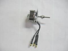
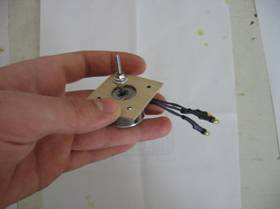
The subsonic closed jet open circuit wind-tunnel has been specifically designed for propulsive and aerodynamic testing of MAV and provides flow velocities in the range of 0-45 m/s which is the operating range of MAV usually. Test-section has been designed in such a way that a 0.4m x 0.4m MAV model or prototype can be mounted inside tunnel for aerodynamic load measurements. For propulsion system testing power and thrust measurement set-up are mounted inside tunnel using various fixtures. This enables in-situ testing of different propeller-engine or propeller-motor combination. Power measurement set-up (PMS) uses a torque sensor at the centre with the propeller and motor mounted on either side of sensor. For principle, one can visualize a central shaft from motor at extreme right to propeller at extreme left passing through sensor. This central shaft is mounted on two bearings, one on either side of the sensor. On one end motor works as prime mover whereas on other end, torque required to run propeller is measured by the sensor. Product of this torque with rotational velocity gives the shaft power (Ps). Power losses in bearings are measured by running the motor on this set-up under no load condition (without propeller) and characteristics of power loss as a function of RPM is obtained. Lower block shown in fig is a channel, selected to minimize the blockage behind the propeller. Inside this channel a small optical RPM sensor is mounted. RPM sensor consists of an infra red light transmitter and a receiver. Light emitted by transmitter is reflected from white patch painted behind the propeller. Receiver generates a count each time it receives reflected light which gives RPM. Thrust measurement set-up (TMS) uses a load cell of capacity suitable for MAV class propellers. DC electric motor clamped between two C-clamps fixed on perspects bench is mounted on one end of load Cell. Other end of load cell is clamped to rigid support. This load cell works as cantilever beam. Thrust produced by propeller acts normal to the vertical axis of load cell and equal amount of force is registered at one end of load cell as shear force. RPM is measured using optical sensors. As this set-up is mounted inside the tunnel for measuring thrust produced by the propeller at different flow velocities, drag produced by set-up is significant. Hence drag coefficient of set-up is obtained experimentally and correction for drag of set-up is also included. Selection of motors for MAVs is done on the basis two parameters, motor efficiency and its shaft power to weight ratio. Higher the value of these parameters better is the motor, given it satisfies absolute sea level power requirement for the vehicle. For IC engine characterization the set-up is an extended version of thrust measurement setup for electric engine. Here objective is measuring TSFC and SFC at different engine RPMs. SFC or TSFC depends on the propeller, engine and fuel (70-75% Methanol, 20% Castor Oil, 5-10% Nitromethane). Along with main thrust measuring load cell, set-up consists of a stand fixed at distance of 20-50mm from propeller. Throttle of engine is controlled using servo rigidly clamped to base plate. Servo controls the throttle through a control rod. External pipe is provided for taking exhaust gases and oil out. 3. Some Aspects about the Micro-Turbojets Integration The microfabricated high-speed gas turbine is modeled after it's more common "macro-scale" counterparts. While the MGT's use as a source of propulsion is very limited in most applications to MAV rather than micro-rockets, both the design and the fabrication process provide important advances to the current state of the art in micro-scale propulsion. MGT has about 20mm square with a depth anywhere between 3-5mm and the main feature is a rotating disk, 8mm in diameter, mounted along a shaft in the middle of the system. The disk is driven by feeding an air/fuel mixture into a chamber surrounding the disk then igniting this mixture to drive the turbine and exhaust the resulting pressurized gas. Because of the complex geometry and relative motion of the components the microfabrication steps to build the micro-turbine engine are quite complicated. Six individual silicon wafers are etched using deep reactive ion etching (DRIE) and then wafer bonded together. This stack-up, makes alignment accuracy a concern during fabrication. Because the pressurized exhaust, and thus the propulsion, is created by the rotating turbine, the speed at which the disk spins in relation to the shaft is also of critical importance to the efficiency of the system. To have a comparable power density to macro-scale turbines used in large-scale propulsion, like airplane engines, micro-turbines must rotate with a rotor tip speed of about 500 m/s, or at approximately 1,200,000 rpm (Fréchette, 2000). While this has been achieved, there are problems in efficiency that arise from this high power density. As larger speeds are reached, energetic losses and the chance of failure increase due to frictional forces. In fact the development of novel, micro-bearings to increase the average 20% efficiency that micro-turbines get is a major focus of current research. While the uses and benefits of micro-turbine engines are clearly there, the problems associated with downscaling rapidly moving parts has been the major stumbling block in fully realizing micro-turbine powered micro-rockets. To have a comparable power density to macro-scale turbines used in large-scale propulsion, like airplane engines, micro-turbines must rotate with a rotor tip speed of about 500 m/s, or at approximately 1,200,000 rpm (Fréchette, 2000). While this has been achieved, there are problems in efficiency that arise from this high power density. As larger speeds are reached, energetic losses and the chance of failure increase due to frictional forces. In fact the development of novel, micro-bearings to increase the average 20% efficiency that micro-turbines get is a major focus of current research. While the uses and benefits of micro-turbine engines are clearly there, the problems associated with downscaling rapidly moving parts has been the major stumbling block in fully realizing micro-turbine powered micro-rockets. 4. Gaseous Propellant Micro- rockets Because of the problems associated with frictional losses and moving parts, some research is being directed towards micro-rockets designed with no moving parts. These designs are expected to be used in future spacecraft and small micro-satellites because of their reusability and the long service life associated with no moving features. The rocket is made from 6 single crystal silicon wafers, each approximately 4" square. To allow for the high aspect ratio features, deep reactive ion etching is used in conjunction with more standard chemical vapor deposition and buffered oxide etching techniques to fabricate the micro-rocket. Unlike the micro-turbine, this rocket gains all of its thrust force from careful design of the chamber and nozzle geometry. Thus, 3D contours must be created using largely 2D micro fabrication techniques, creating a challenging and relatively slow process. The difficulties in micro fabrication are more than made up for in the success of the device, however. Recent tests on the first generation liquid cooled, gaseous propelled micro-rocketwere largely successful; the device created a good thrust, useful thrust power and thrust to weight ratio (twr).Future tests planned to increase the chamber pressure by an order of magnitude, experimenters expect that the gaseous propelled rocket will eventually yield up twr. While the micro-turbine and the gaseous propelled rocket are both steps forward in micro propulsion, they both have disadvantages: difficult fabrication procedure and the need for a bulky external system to provide the liquid and gaseous fuel components. Solutions to these problems have been explored in the solid propellant rocket. 5. Solid Propellant Micro- rockets for Vertical Take- off This design has a lower total thrust force than the gaseous propelled rocket (0,2-5 N thrust and 2,5-10 Ns impulse), but has the ability to provide a substantially greater energy density than conventional batteries and other small power sources. The solid propellant rocket design also has the advantage of being easier to fabricate and customizable in regards to fuel selection. The main limitation (Rossi, 2002) could be overcome by fabricating large arrays of rockets and using a digital control scheme to control the firing. The size of the solid propellant combustion chamber and nozzle make assembling arrays feasible. The specific design and current performance progress of the solid propellant micro rocket is of particular interest because of the greatest opportunity for advancements in micro-satellite and other future small spacecraft propulsion. The solid propellant rocket is relatively easy to fabricate with simple techniques such as anisotropic etching and the fuel source is both customizable and self-contained. The high energy density makes this design the best choice for space-based applications. Thus, to fully explore the cutting edge of micro-rocket research, an in depth case study will follow which focuses on the specific attributes of the solid propellant micro-rocket. The design's step-by-step fabrication techniques and geometric and materials considerations will be examined in an effort to fully realize the extent to which this design has revolutionized both micro-propulsion and the use of micro-rockets. An analysis of some of the fabrication methods utilized in microrockets with solid propellant was presented in detail by Rossi (2002). This is a simple design with microrocket components with cylindrical shapes; all components, due to anisotropic etching constraints, are limited to rectangular and pyramidal shapes. This fabrication technique is lacking certain details that can be filled in using inferences from the procedure and other sources pertinent to the topic. The fabrication of this design can be broken down by its components: a convergent/microheater, propellant chamber and divergent. a) Propellant Chamber The propellant chamber should be made of a material with a low thermal conductivity so that less thermal energy from the combustion of the fuel leaks out and more thrust can be obtained from the rocket. Silicon, while amenable to established micromachining processes, may not be the optimal choice in this respect given its moderately high thermal conductivity. On the other hand, ceramic materials can have a thermal conductivity 4 -10 times less than silicon and can be considered as an alternative material for the construction of the fuel chamber. For microscale applications, chambers can be fabricated by conventional drilling, in this case using the commercial ceramic MacorR (Corning). Tab. 1 gives a comparison of selected properties of silicon and Macor®. Micromachining the ceramic becomes somewhat of an issue for smaller size scales, although the possibility of adapting ceramic injection micromolding techniques for this application is promising.
b) Solid propellant for vertical take off micro rockets These propellants are preferred for their stability and relatively high energy density. A composite fuel consists of a binder material (polybutadiene or glycidyle azide polymer), an oxidizer (NH4ClO4), and a metallic fuel (Al, Zr, B, Mg). While composite propellants have a relatively low specific heat value and leave metallic particle residue after combustion, they have a greater specific impulse than homogeneous fuels such as nitrocellulose or nitroglycerine and are low vulnerability ammunititions. In particular, the mixtures can be adapted such that the rheological, ballistic and kinetic properties are optimal for the given application. 5. Conclusion Literature survey analysis reveals that performance of propulsion system plays critical role in overall sizing and performance of micro and mini class aerial vehicles. Hence availability of experimental facilities for accurate power plant characterization is basic requirement for development of MAVs. Different experimental facilities were designed and developed for experimental characterization of clasical MAV power-plant. Validation of results obtained using these facilities with those available in literature reinforced the reliability of these facilities. Our infrastructure was successfully used to determine the required characteristics of propeller, engine and motor which are being considered for design of a variable geometry vertical take off MAV with hydride propulsion system. Propeller characterization tests results show that propellers available in market are customized and have efficiency in the range of 650% to 80%. Literature survey and blade element theory based analytical tool reveals that propeller design can be improved to give efficiency of the order of 85% for any given operating range. The optimization of propeller design for given requirements of MAV is very important and the flight tests must integrate adequately the hybrid propulsion system. Optimized propeller was developed using analytical tool (Blade element theory) coupled with an dedicated optimizer. Prototype based on optimized design was tested experimentally and in real flight. Similarly, by testing set of motors, motor of higher efficiency and higher shaft power to weight ratio for given seal level power condition can be selected. Based on historical data and experience, DC motor is best suitable for low endurance flight and low weight whereas IC engine is best suitable for high endurance flight and heavy MAVs. So mission requirements primarily govern the choice among these two. The vertical take off condition need also a solid propellant micro rocket. In utilizing various techniques of micro fabrication, it is possible to scale a propellant system down to dimensions of technological interest. It was analyzed the fabrication process, design considerations and performance resulted from a solid-propellant micro-rocket system. It was demonstrated the advantages. In particular, the solid-propelled micro-rocket is an interesting solution relative ease of fabrication and low cost, fuel energy density, and efficiency. To be able to apply appropriate techniques of fabrication reliably on such a small scale will inevitably enable the production of such useful devices to flourish. Materials considerations allowing for structural stability and fuel efficiency, including a larger specific impulse for composite propellants than traditional fuels, is one of the leading motivations in continuing this design. Integrating micro rockets into the vertical take off device will improve the overall performances of the MAV hybrid propulsion systems which are better fitted on a variable geometry MAV. 6. Reference 1. Livermore, Carl. "Here Come the Microengines." The Industrial Physicist. Vol 7, Issue 6. December/January 2001. 2. Fréchette, Luc G., Demonstration of a Microfabricated High-Speed Turbine Supported on Gas Bearings. Solid-State Sensor and Actuator Workshop, Hilton Head Is., SC. June 4-8, 2000. 3. Rossi, C. "Design, Fabrication and Modeling of Solid Propellant MicroRocket-Application to Micropropulsion." Sensors and Actuators: A Physical. Vol 99. 2002. 4.Boscoianu, M, Some aspects about the new opportunities offered by a small size HALE UAV, Budapest, International Conference Miklos ZrInyI Military University, 18-19 oct 2005. 5. Coman, A, Safta, D, Boscoianu, M A Method for Optimising the Stability of Flight Velocity of Modern Aerospace Propulsion Systems 57th IAC Congress, Valencia, Spain, October 02-06 2006. |
© ZMNE BJKMK 2006.